We use cookies to improve your experience and deliver personalized content. Cookie Settings
Frequently Asked Questions – Ventway
Transport ventilators are designed to take the place of manual ventilation or “bagging” during emergency or transport situations. They are mainly used for interhospital, intrahospital, or prehospital emergency transport.
The Ventway Sparrow ventilator is intended to provide continuous or intermittent ventilatory support for the care of individuals who require mechanical ventilation.
The ventilator is a restricted medical device intended for use by qualified, trained personnel under the direction of a physician.
The Ventway Sparrow has been approved by the FDA, CE, TGA, AMAR as well as other local regulation registries. For your specific territory please contact Info@inoytec.com
The Ventway has three models each one tailored to the specific needs of our clients.
- The Ventway Sparrow EMS & TRANSPORT, for use by civilian emergency services.
- The Ventway Sparrow HOSPITAL TRANSPORT (MRI) for in-hospital use.
- The Ventway Sparrow ROBUST, for use helicopters, airplanes, ambulances, hospital ships, combat support hospitals, front line stations and combat situations.
The Ventway’s unique combination of functionality and compact design offers unmatched performance to its users and an unparallel continuum of care to its patients.
The Vantway is used in over 20 countries and has been adopted by leading EMS, militaries and healthcare care organizations around the world.
Yes. The Ventway Sparrow Models VWSP-100MR and VWSP-900MR are designed and shielded to ventilate patients in the vicinity of an MRI scanner and can be used at a magnetic field strength of 47 mT (470 G) without creating any MR image artifacts.
Yes. The Ventway Sparrow is designed to operate at an altitude of -370 to 7620 meters (-1,200 to 25,000 feet).
A: In adult patients, it’s 6-8 cc/kg. When weight becomes smaller this value is increased (e.g., 15 kg). For pediatric it is 10-12 cc/kg and reduces as weight increases.
The FiO2 valve does not have linear increments.
Ventway supports multiple languages including English, German, Chinees, Russian, Japanese and more.
The Ventway can be configured with two Lithum-ion battery options: a re-chargeable battery pack, and a non-rechargeable battery pack.
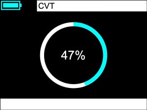

The Circuit Verification Test (CVT) is the first procedure a user will be asked to perform after turning on the ventilator, it verifies the patient circuit’s operational function.
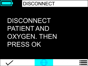
Performing the Circuit Verification Test (CVT) is extremely simple. When the disconnect patient screen appears connect the patient circuit to the Ventway Sparrow and press “confirm”.
The system will activate the blower for about 10 seconds during which the CVT screen will be displayed.
Should a CVT failure occurs the user is advised to check the following:
- The patient circuit is properly connected to the ventilator’s outlet.
- The blue protective cap that arrives with the patient circuit has been removed.
- The inspiratory tube is not deformed and there is nothing that obstructs or occludes it.
- The oxygen mixer is not connected to the ventilator.
- The oxygen reservoir is not connected to the ventilator.
- There is no HME filter connected to the patient circuit.
- There is nothing that obstructs or occludes the inlet filter.
- The sensing tubes are properly connected.
- The sensing tubes are not deformed and there is nothing that obstructs or occludes them.
The Ventway offers the following ventilation modes:
| Term | Classification | Description |
| SIMV PC (PS)
|
PC-IMV
|
Pressure Control Synchronized Intermittent Mandatory Ventilation with pressure support ventilation – Mandatory breaths are pressure controlled and spontaneous breaths are pressure supported
|
| SIMV VC (PS)
|
VC-IMV
|
Volume Control Synchronized Intermittent Mandatory Ventilation with pressure support ventilation – Mandatory breaths are volume-controlled and spontaneous breaths are pressure supported
|
| CPAP (PS)
|
PC-CSV
|
Continuous Positive Airway Pressure
|
| CPAP (PS) HF
|
PC-CSV
|
Continuous Positive Airway Pressure
|
For SIMV-PC (PS)
| Ideal Body Weight (Kg) | Rate
(BPM) |
Tidal Volume
(ml) |
I:E Ratio
|
FiO2
(%) |
PEEP
(cmH2O) |
| 5 | 35 | 50 | 1:2 | 21 | 5 |
| 10 | 30 | 70 | 1:2 | 21 | 5 |
| 15 | 23 | 100 | 1:2 | 21 | 5 |
| 20 | 20 | 120 | 1:2 | 21 | 5 |
| 30 | 18 | 180 | 1:2 | 21 | 5 |
| 40 | 16 | 240 | 1:2 | 21 | 5 |
| 50 | 14 | 300 | 1:2 | 21 | 5 |
| 60 | 12 | 360 | 1:2 | 21 | 5 |
| 70 (+) | 12 | 450 | 1:2 | 21 | 5 |
For SIMV-VC (PS)
| Ideal Body Weight (Kg) | Rate
(BPM) |
Inspiratory Pressure
(cmH2O) |
I:E Ratio
|
FiO2
(%) |
PEEP
(cmH2O) |
| 5 | 35 | 15 | 1:2 | 21 | 5 |
| 10 | 30 | 15 | 1:2 | 21 | 5 |
| 15 | 23 | 15 | 1:2 | 21 | 5 |
| 20 | 20 | 20 | 1:2 | 21 | 5 |
| 30 | 18 | 20 | 1:2 | 21 | 5 |
| 40 | 16 | 20 | 1:2 | 21 | 5 |
| 50 | 14 | 20 | 1:2 | 21 | 5 |
| 60 | 12 | 20 | 1:2 | 21 | 5 |
| 70 (+) | 12 | 20 | 1:2 | 21 | 5 |
For CPAP (PS)
The default pressure support level is 18 cm H2O.
The following table summarizes the various types of alarms.
| Alarm Type | Value | Range/Display |
| User Adjustable
|
Breath rate | High: 12-70 (BPM)
Low: 1-20 (BPM) |
| Apnea | 10-120 (Seconds) | |
| Leak | 10-100 (%) | |
| Low Tidal Volume Delivered | Off or 15-85 (%) | |
| Inverse I:E Ration | ON/OFF | |
| Alarm Volume | 1-4 | |
| Pressure Limit | 11-60 (cmH2O) | |
| Pressure Alarm Limit | 10-55 (cmH2O) | |
| Additional | Low Battery | Estimated Battery Energy Level + Alarm |
| Empty Battery | Screen Icon + Alarm | |
| Battery Disconnected | Screen Icon (Swapping) | |
| Sensor Tube Disconnected | Alarm | |
| Tube Disconnected | Alarm | |
| Patient Disconnected | Alarm | |
| High PEEP | Alarm | |
| Low PEEP | Alarm | |
| Service Notice | Alarm | |
| System Boot Failed | Alarm | |
| AC Power Disconnected | Screen Icon + Audio Que |
Alarms are defined with three levels of importance:
- High: Five beeps every two seconds
- Medium: Three beeps every five seconds
- Low: One beep one time only. Not shown in list of active alarms.
The following table summarizes the various alarms according to their level of importance:
| Alarm Category | Alarm |
| High Level
|
Blower Malfunction |
| Tube Disconnect | |
| Patient Disconnect | |
| Apnea | |
| System Recovered from a Crash | |
| Battery Empty | |
| Sensor Disconnect | |
| Low Respiratory Rate | |
| High Minute Volume | |
| Low Minute Volume | |
| High Inspiratory Pressure | |
| Low Inspiratory Pressure | |
| Leak | |
| Inverse I:E Ratio | |
| High Temperature | |
| Expiratory Valve Blocked | |
| High PEEP | |
| Low PEEP | |
| Medium Level
|
High Breath Rate |
| Tidal Volume Limit Reached | |
| Low Tidal Volume | |
| Low Pressure | |
| Battery Low | |
| High Voltage | |
| Low Level
|
Low Level |
| Replace Filter | |
| Service Needed | |
| Altitude Out of Range | |
| Unexpected Restart |
The following table indicates the default alarm parameters according to the selected Ideal Body Weight:
| Alarm Parameter
|
Ideal Body Weight | ||||||||
| 5Kg | 10Kg | 15Kg | 20Kg | 30Kg | 40Kg | 50Kg | 60Kg | 70Kg(+) | |
| Pressure Alarm (cmH2o) | 21 | 23 | 25 | 30 | 30 | 30 | 30 | 30 | 30 |
| Pressure Limit (cmH2o) | 25 | 28 | 30 | 35 | 35 | 35 | 35 | 35 | 35 |
| High Rate (BPM) | 45 | 40 | 35 | 30 | 30 | 30 | 30 | 25 | 25 |
| Low Rate (BPM) | 12 | 10 | 10 | 10 | 8 | 6 | 6 | 6 | 6 |
| High Min. Vol. (LPM) | 3.5 | 4.2 | 4.6 | 4.8 | 6.4 | 7.6 | 8.4 | 8.6 | 10.8 |
| Low Min. Vol. (LPM) | 0.9 | 1 | 1.1 | 1.2 | 1.6 | 1.9 | 2.1 | 2.1 | 2.7 |
The following table indicates the default alarm parameters valid for all patients’ weights:
| Alarm Parameter | Set Value |
| PEEP (cmH20) | > 2.5 cmH2O from Set Value |
| Low Pressure (cmH20) | 5 cmH2O |
| Leak (%) – Noninvasive Ventilation | 100 % (Off) |
| Leak (%) – Invasive Ventilation | 25 % (Adjustable) |
| Inverse I:E Ratio (ON/OFF) | ON |
| Low Tidal Volume Alarm Range (%) | 85 % of Set Volume |
For additional information please see the Ventway Sparrow’s instructions for use (IFU).
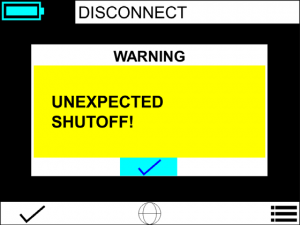
An Unexpected Shutoff alarm will be displayed in the event of a power loss that caused a shutoff of the ventilator.
- If power is lost during ventilation and the ventilator is turned on within 2 minutes, it will automatically start with ventilation, and a DISCONNECT alarm of unexpected shutoff will be displayed on the screen.
- If power is lost during ventilation and the ventilator is turned on after more than 2 minutes, the operator will be asked if he wants to continue ventilating using the previous parameters.

During high temperature operation, the ventilator may prompt an alarm re-garding its high temperature charge limit. The battery protection circuit will stop charging below 0°C and over 50°C, as measured inside the battery pack.
Normal ventilator operation may create heat in the battery compartment. When operating in a hot environment you should remove the ventilator padded case, increasing heat dissipation into the environment.
During low temperature operation, it is recommended to use the ventilator padded case. This will insulate the unit from the outside temperature and retain the internal heat created by the blower motor and other electrical heat-generating components.
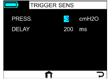
To adjust the trigger sensitivity, follow these steps:
Go to MENU -> VENT.PARAMS -> TRIGGER SENS. -> PRESS (cmH2O)/DELAY (ms)
To change the preset display of the Tidal Volume, follow these steps:
Go to MENU -> ADV.SETTINGS -> SCROLL DOWN -> VENT. DISPLAY -> Select the desired parameter.

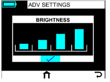
To adjust the brightness of the screen, follow these steps:
Go to MENU -> ADV.SETTINGS -> BRIGHTNESS -> Select the desired level.
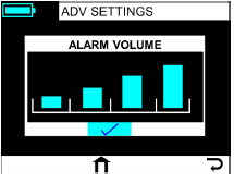
To adjust the alarm volume, follow these steps:
Go to MENU -> ADV.SETTINGS -> ALARM VOL. -> Select the desired level
No. The Ventway Sparrow’s patient circuit is designed for ease of operation, the inspiratory tube can only be connected to the ventilator patient outlet at the front panel of the device and the same can be said to the sensing tubes which will be connected to the sensing port located next to the ventilator patient outlet.
To use the oxygen mixer, connect its plastic tube to the Ventway Sparrow’s air/oxygen inlet port located in the back panel of the device and screw it to secure it in place. The connector is specially threaded to fit securely on top of the air/oxygen inlet.

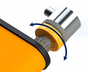
The Oxygen Mixer may be adjusted to mix atmospheric air and oxygen in ratios between 30% to 95%. The user may change the oxygen percentage of the gas mixture by rotating a knob at the base of the Oxygen Mixer.
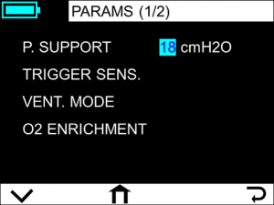
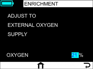
Once you’ve set the Fio2 adjust the “O2 coefficient” parameter in the device to align with Fio2 you have set in the oxygen mixer. To do so Go to MENU -> VENT.PARAMS -> O2 ENRICHMENT and set the value.
Note:
- The high-pressure connection to the Oxygen Mixer should be performed using a standard female DISS connector.
- The oxygen supply pressure shall be according to manufacturer specifications (usually 40-60 psi).
- Measure FiO2 with a calibrated external oxygen analyzer.
As with the high-pressure oxygen mixer, once you’ve set the Fio2 adjust the “O2 coefficient” parameter in the device to align with Fio2 you have set in the oxygen mixer. To do so Go to MENU -> VENT.PARAMS -> O2 ENRICHMENT and set the value.
The Ventway Sparrow has an external PEEP valve that us located at the patient side of the patient circuit. The PEEP value is displayed at the lower left side of the ventilation parameter screen (see image below). The PEEP value will be preset to 5 cmH20, however this must be verified by the value shown on the ventilator screen. To adjust the value, rotate the PEEP knob right or left to increase or decrease the PEEP.
Note: When setting the PEEP value, make sure that there are no kinks in the three tubes.

The Ventway Sparrow has an external PEEP valve that can provide 0-20 cmH2O (+1 cmH2O)
YES. PEEP value may be influenced by the oxygen enrichment method in extreme cases when ventilation operation is stopped and re-started.
For example, if we connect an Oxygen Mixer for O2 enrichment, the PEEP may decrease at 3-4 cm H2O. Although the ventilator will issue an alarm, the user may have to readjust the PEEP by rotating the PEEP knob.
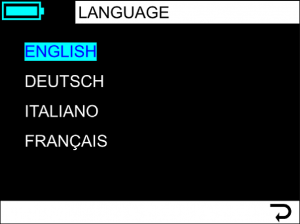
The Ventway Sparrow operates in multiple languages, to change the default English language, rotate the scroll knob to the Language symbol, press it and select the required language.
The system requires maintenance on a routine basis in accordance with Ventway Sparrow Service Manual. Service should only be provided by an authorized Inovytec Medical Solutions Ltd. representative. For further information please refer to the Ventway Sparrow Service Manual.
The Ventway Sparrow and its accessories must always be clean. Clean the ventilator’s external surfaces after each patient use.
This Ventway Sparrow requires routine cleaning, which includes removal of any soil or dirt from its external surfaces. A soft cloth dampened lightly with water may be used.
- Spray the entire surface of the device with 70% alcohol.
- Leave the alcohol on the device for an exposure time of 2-3 minutes.
- Wipe the surface of the device with Pharma-Wipes 70% alcohol.
Inspect the device for residual debris. Should any debris remain, repeat the entire cleaning procedure until all debris are removed.
The inlet filter should be replaced after 300 hours of use, the ventilator will automatically alert you when the time for this action has come.
In case that dust, sand or some other visual debris appears on the inlet filter or in case of any damage, the filter must be replaced before using the device.
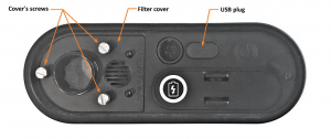
To replace the inlet filter, use a flat screwdriver to release the 3 screws in the filter cover on the back panel of the device. Take out the old filer and replace it with a new one. Check the one-way valve on the inner side of the filter cover, verify that it is in place and not deformed, close the filter cover and tighten the screws by hand, do not use tools to tighten the screws.
The system requires routine calibration every three years or after SW update. Calibration should only be performed by an authorized Inovytec Medical Solutions Ltd. representative.
For further information on how to perform the calibration please refer the Ventway Sparrow Service Manual.
Rechargeable Battery
To maximize the lifetime of the rechargeable battery (shelf-life of 4 years), it should be stored at a temperature range of 10°C to 35°C (32°F to 95°F) and fully charged every 6 months. In these conditions the shelf life of the battery is expected to be 4 years or 500 cycles of fully charge and discharge
Non-rechargeable Battery
To maximize the lifetime of the non-rechargeable battery (shelf-life of 5 years), it should be stored at a temperature range of -20°C to 35°C (-4°F to 95°F).
While not using the device, the recommended temperature storage is -20°C to +70°C (-4°F to 158°F), it is recommended to store the battery separately from the device.
It is strongly recommended to store the device in its case where it is protected from dust, sand and water.